
Did you get yourself a multimeter and are unsure what to do with it? Don’t worry—I am here for you. I will show you how to use a 7-function digital multimeter to troubleshoot electrical problems in the simplest way possible. So, are you ready? It’s going to be fun. Let’s do this!
My Best Recommendation!

- VoltAlert technology for non-contact voltage detection
- AutoVolt automatic AC/DC voltage selection. DC millivolts – Range : 600.0 mV, Resolution : 0.1 mV
- Low input impedance: helps prevent false readings due to ghost voltage
Last update on 2026-04-05 / Affiliate links / Images from Amazon Product Advertising API
Understanding Your 7-Function Digital Multimeter
Let’s understand our multimeter before we step into the usage and functions.
What is a Multimeter?
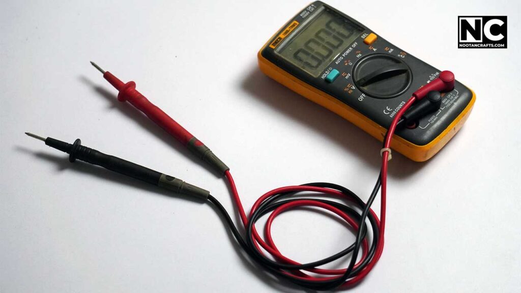
A multimeter is a measuring instrument that allows you to measure different electrical properties in a single unit.
Let’s understand it this way: A voltmeter and an ampere meter are independent instruments used to measure voltage and ampere in a circuit, respectively. On the other hand, a multimeter can perform both of these functions (and usually more) in a single unit.
Usually, a multimeter (including analog) offers voltage, current, and resistance measuring functions. Seven-function digital multimeters are more advanced; they can perform additional tests such as diode, transistor, and battery. Don’t worry too much for now, because trust me, at the end of this article, you’ll be able to perform all the tests easily.
Altogether, a multimeter is an essential tool in diagnosing electrical problems.
Now, let’s talk more about a multimeter’s parts. Why the heck are so many numbers and weird symbols printed on a multimeter, and what to do with two leads?
Key Components of a 7-Function Digital Multimeter
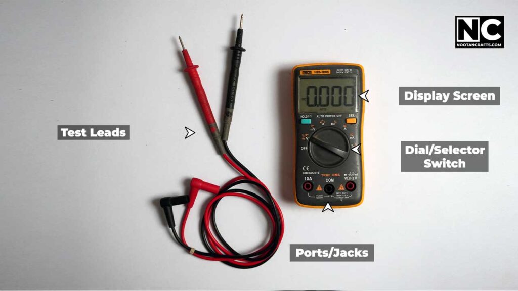
Display Screen: The screen shows the measurement results whenever you connect test leads in any circuit. Digital multimeters usually come with an LCD that provides clear and accurate readouts.
Dial/Selector Switch: The dial allows you to select different measurement functions and ranges. That’s the beauty of a multimeter: Just rotate the dial, and your multimeter will act as a totally different measuring device. However, it’s crucial to set this correctly to avoid damaging the device or getting inaccurate readings. We will talk about it later.
Ports/Jacks: These are where you plug in the test leads. Typically, there are three ports: COM (common ground), VΩ (voltage and resistance), and mA/10A (current measurements).
Test Leads: These are the probes you use to contact the circuit or component you’re testing. They come in two colors: red (positive) and black (negative).
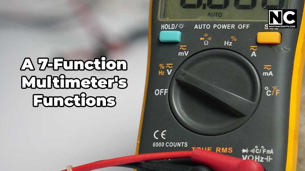
Okay, we are now familiar with the parts of a simple multimeter. Let’s take a broad overview of what we can measure with a typical 7-function multimer.
Remember, every brand of multimeter is different and offers different functionality, so first read its manual. However, the primary function and indications are the same, which you’ll understand shortly.
Here are the basic tests that a 7-function multimeter can perform.
A 7-Function Multimeter’s Functions and Their Uses
Continuity Check
The most basic function of a multimeter is to check whether a circuit is open. You can test wires, fuses, switches, and any circuit to test its continuity. This function is generally used when there is no current in the circuit.
Measuring AC Voltage
This function is used to check the Alternating Current (AC) voltage found in our power outlets (often marked as V~). We use this to verify electrical outlets, troubleshoot appliances, inspect wiring, and ensure the proper operation of light fixtures, HVAC systems, smoke detectors, water heaters, electrical panels, etc.
Measuring DC Voltage
To measure the Direct Current (DC) voltage, rotate the knob to the DC range (marked as V—). With this function, you can check batteries in remote controls, flashlights, and other gadgets, troubleshoot DC-powered appliances, verify solar panel output, etc. You can also test different kinds of batteries in this range, such as lithium-ion and lead acid.
Measuring Current AC/DC
This function allows you to calculate the current consumed by an appliance, troubleshoot circuits, and ensure that circuits are not overloaded. You have to set the meter range to ampere (usually market with A~).
Battery Testing
A 7-function multimeter comes with a dedicated battery testing range. You can also use the DC voltage range; just make sure to set the multimeter at a higher range than the battery’s voltage.
Measuring Resistance
Resistance is measured in ohms (Ω). This function allows you to check the resistance between two points in the circuit, which is mostly used to check components like Resistors.
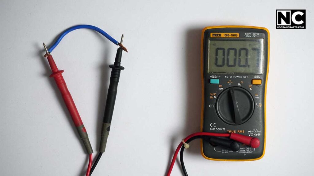
Testing Diodes and Transistors
This function allows you to verify the integrity of components like diodes and transistors. At this range, the meter drops around 0.6 – 0.7 volts when you test a diode or transistor in forward bias. Don’t worry; we will discuss it in detail in a step-by-step guide.
Now, you have a broad overview of the basic functionality of a 7-function multimeter. Remember, more advanced multimeters allow measuring even more properties, such as frequency, capacitance, and temperature. We will discuss advanced multimeters later in another article. For now, let’s focus on our main topic: how to use a 7-function multimeter.
Safety Tips for Using a Multimeter

Using a multimeter, especially on a live AC circuit, is risky. Therefore, I advise you to take proper precautions. Wear safety glasses and gloves when dealing with higher voltage.
Apart from personal safety, you have to be very attentive when selecting the range on a multimeter. Always double-check the dial settings before taking measurements—trust me, it happens a lot! Incorrect settings can damage the multimeter or provide inaccurate readings.
Note: Keep your work area dry and free from conductive materials to prevent short circuits and electrical hazards.
Step-by-Step Guide to Using a 7-Function Digital Multimeter
Preparation: Before taking any measurements, always check your multimeter’s battery level and lead for damage, as this can result in incorrect readings.
Performing Measurements:
How to Test Continuity With a 7-Function Multimeter?
It’s used to check the broken connection between two points. You can test wires, fuses, switches, and circuits for continuity. Here is how to use a 7-function digital multimeter to test continuity.
- Turn the dial to continuity mode.
- Insert the leads into the COM and VΩ ports.
- Touch the probes to the points you want to check.
- Listen for the beep indicating continuity.
- A beep means the circuit is intact. No beep means a broken connection.
How to Measure Voltage With a 7-Function Multimeter?
When testing voltage, always ensure safety. Especially if you’re dealing with higher voltage, always wear gloves to avoid unwanted skin contact and shock. Here is how to use a 7-function digital multimeter to measure voltage in a circuit.
- Turn the dial to the appropriate voltage setting (AC or DC).
- Insert the black lead into the COM port and the red lead into the VΩ port.
- Touch the probes to the points you want to measure.
- Read the voltage on the display.
Special note: Always set your meter at a higher range than the potential circuit voltage. For example, if you’re testing a 9-volt DC battery, set your meter at 20 volts. For testing mains AC110 volts, set your meter at 200 volts.
How to Measure Current (Amps) With a 7-Function Multimeter?
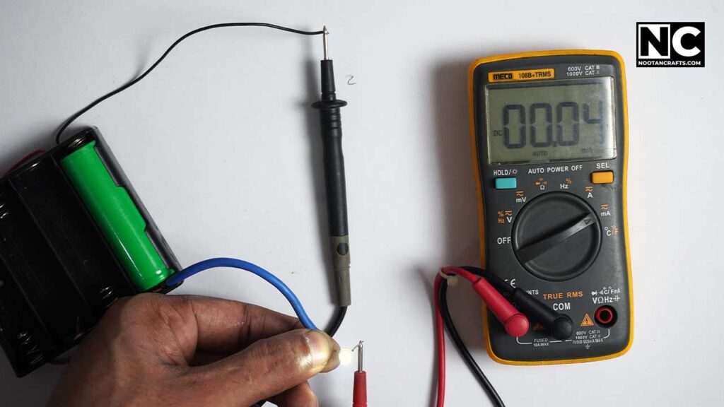
Measuring current is a bit tricky. You have to use the meter in series to perform this test. Also, you need to plug the red probe into the 10A socket. The black lead is always connected to the COM port. Here is how to measure current with a digital multimeter.
- Turn the dial to the current setting (AC or DC).
- Insert the leads into the COM and mA/10A ports.
- Break the circuit and connect the multimeter in series.
- Read the current on the display.
Special note: Never connect the meter for a longer time when testing current across any circuit. Continuously testing higher amperes can damage your meter.
How to Test Batteries With a 7-Function Multimeter?
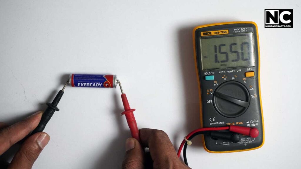
This function is similar to the voltage testing range, but it only supports 1.5 to 9 volts and is specially designed for testing batteries. Here is the process of testing a battery with a digital multimeter.
- Turn the dial to the battery test or DC voltage setting.
- Insert the leads into the COM and VΩ ports.
- Touch the probes to the battery terminals.
- Read the voltage on the display.
Special note: If you’re testing the battery on the DC range, choose the higher range than the battery voltage.
How to Measure Resistance With a 7-Function Multimeter?
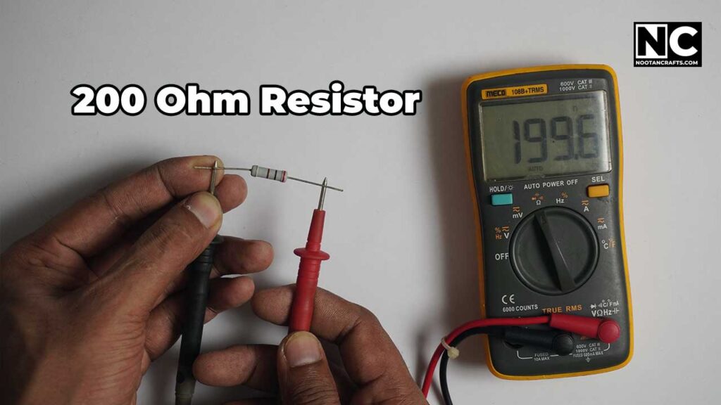
Resistance testing is an advanced version of continuity testing. It will not only tell you whether a circuit is open or closed but also how much resistance it has. You can test continuity with resistance mode but not vice versa. Let’s see how you can measure resistance with a 7-function multimeter.
- Turn the dial to the resistance setting (Ω).
- Insert the leads into the COM and VΩ ports.
- Touch the probes to the points in the circuit.
- Read the resistance on the display.
Special note: Don’t worry about the highest accuracy. Every electrical component has a tolerance value, so it may show a slightly different reading. For example, a 100Ω resistor can show 95Ω or 105Ω (depending on the quality), which means it’s okay.
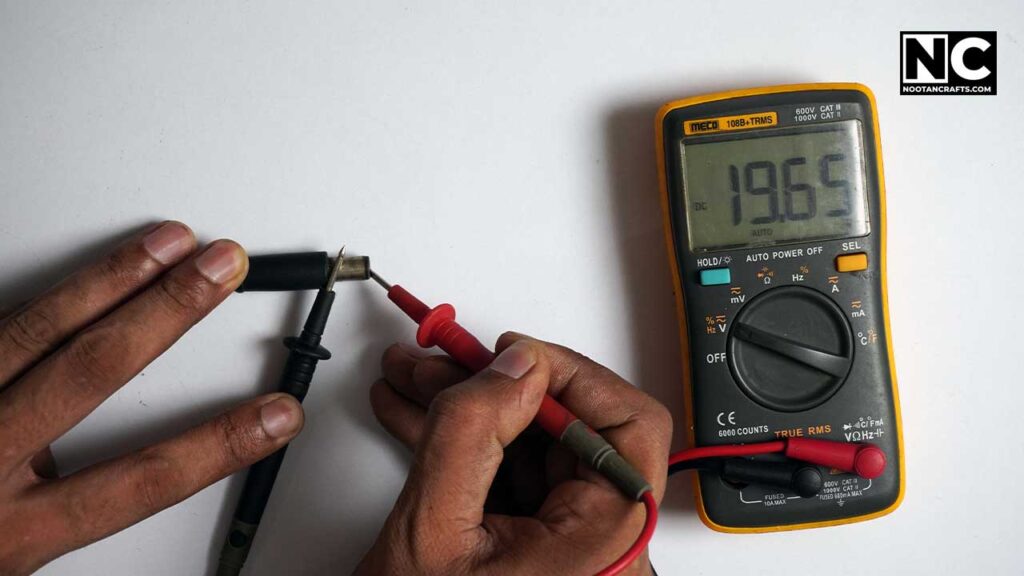
How to Test Diodes and Transistors With a 7-Function Multimeter?
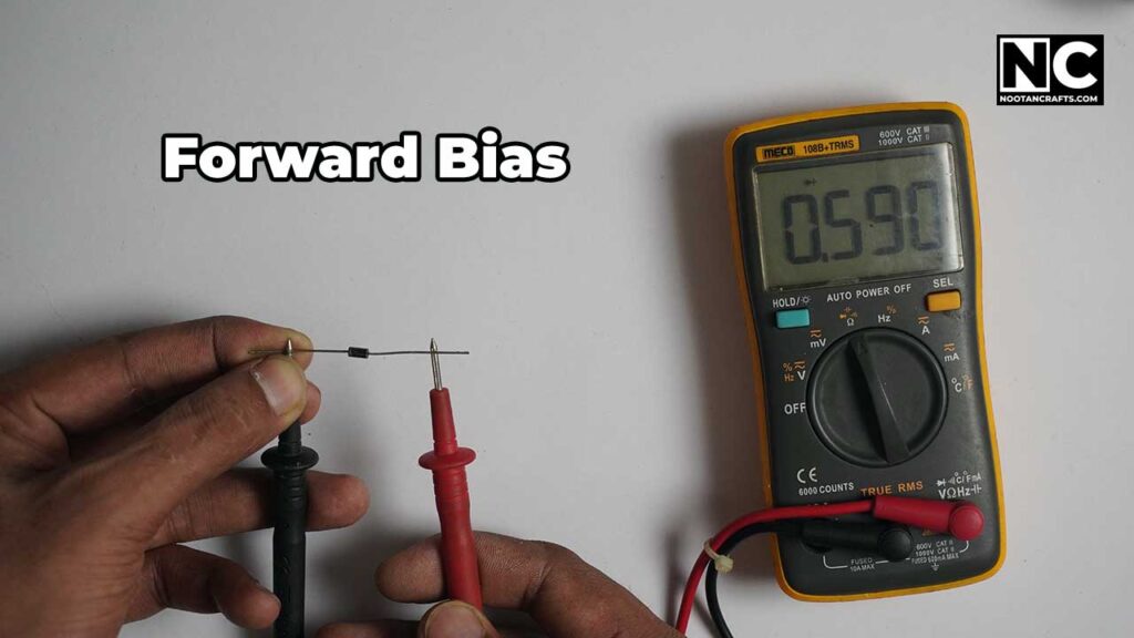
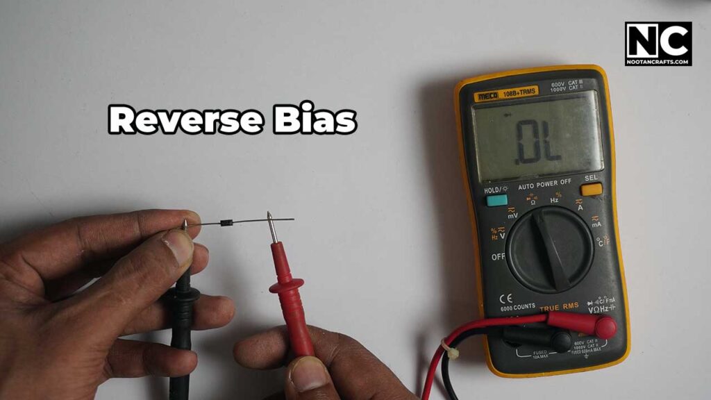
Testing diodes and transistors is a bit tricky because these components need to be tested by changing the probe’s direction. A healthy diode only shows a value in forward bias. If you change the probe direction, it won’t show any value. Don’t worry; here is a step-by-step guide to testing a diode and transistor with a digital multimeter.
First, let’s talk about how to test a diode with a digital multimeter.
How to Test Diodes Using a Digital Multimeter?
- Set the multimeter to diode testing mode.
- Insert the leads into the COM and VΩ ports.
- Touch the probes to the diode leads.
- Read the voltage drop on the display.
Here is the table to help you understand the meaning of these values.
Diode Testing Chart
| Test Condition | Red Probe Position | Black Probe Position | Expected Result | Interpretation |
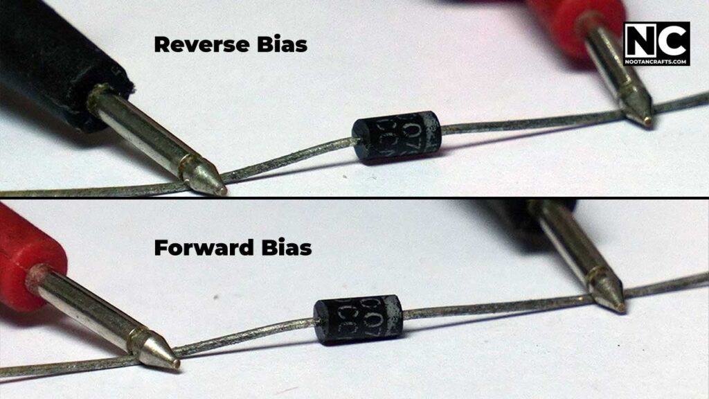
| Forward Bias | Anode | Cathode | Voltage drop (0.6V – 0.7V for silicon diodes) | Diode is functional |
| Reverse Bias | Cathode | Anode | No reading (open circuit) | Diode is functional |
| Both Directions | Anode/Cathode | Cathode/Anode | No reading (both ways) | The diode is open (faulty) |
| Both Directions | Anode/Cathode | Cathode/Anode | Reading in both directions | Diode is shorted (faulty) |
How Do You Test a Transistor with a Digital Multimeter?
Now, let’s come to the transistor testing. According to their composition, there are two types of transistors: NPN and PNP. Therefore, you have to follow the testing procedure according to their nature.
You can understand a transistor as two diodes sandwiched together, and their contacting point has a common leg. Every transistor has three legs: base (B), collector (C), and emitter (E). Fundamentally, a transistor’s testing is a bit similar to a diode’s. I mean, at one time, you’ll test a transistor’s one junction, which acts as a diode.
That’s enough; let’s see this in action. Here is how to test a transistor with a digital multimeter
Steps for Testing NPN Transistors
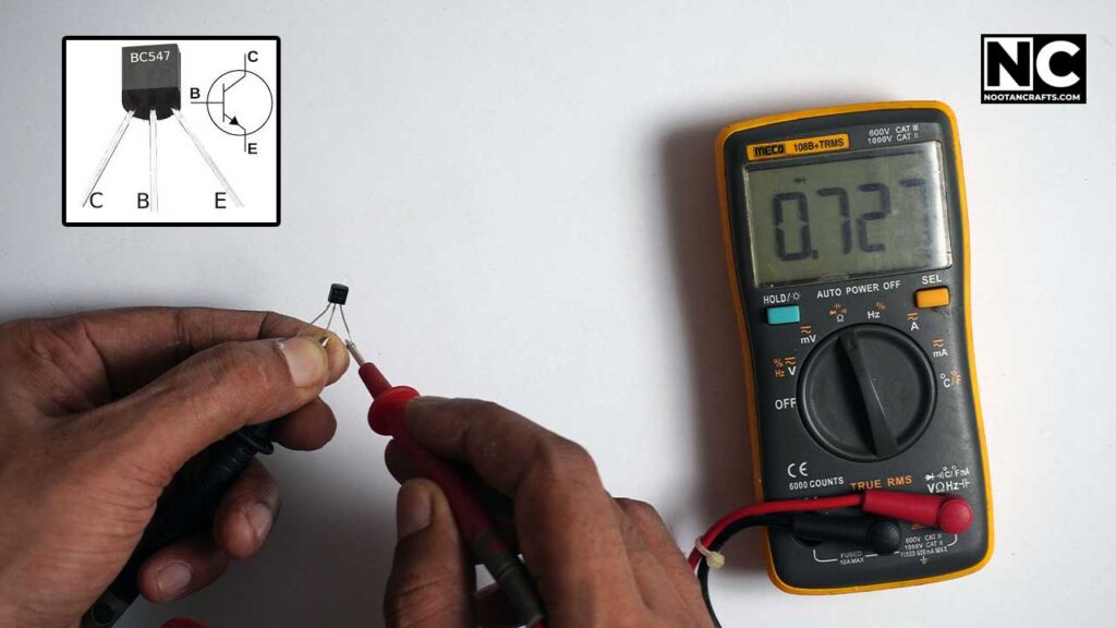
Rotate the multimeter dial to the diode testing mode.
Identify the transistor legs: base (B), collector (C), and emitter (E). In our example, I am testing a BC547 transistor, which has pinout as follows:
- Pin 1 – collector
- Pin 2 – base
- Pin 3 – emitter
Let’s start the process.
Test the Base-Collector Junction
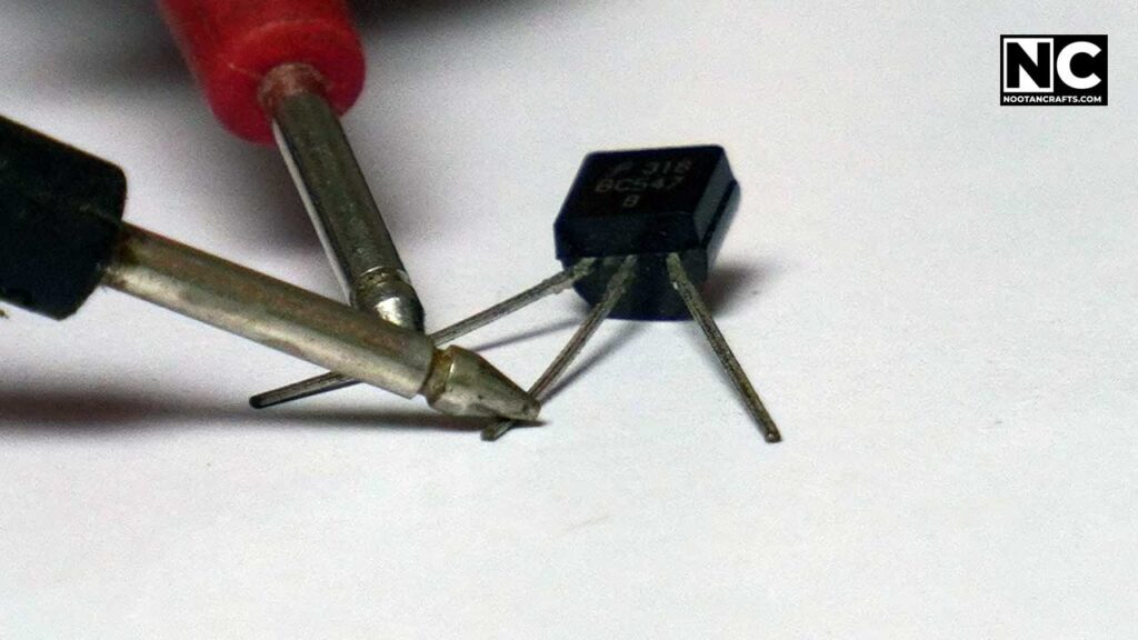
- Connect the red (positive) probe to the base (B) and the black (negative) probe to the collector (C).
- A healthy NPN transistor will show a voltage drop (typically around 0.6V to 0.7V).
- Reverse the probes: connect the black probe to the base and the red probe to the collector. There should be no reading or high resistance.
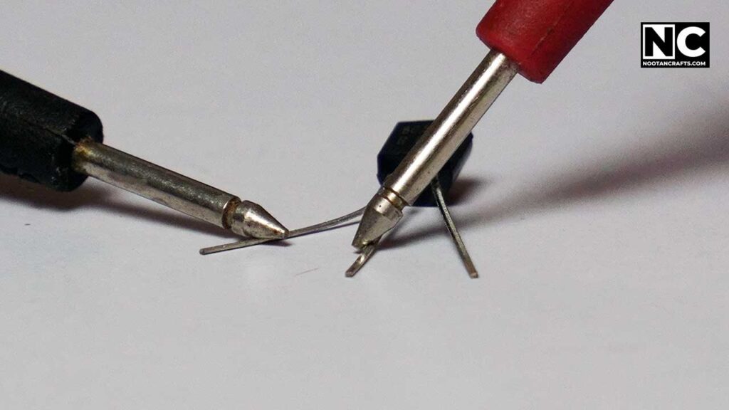
Test the Base-Emitter Junction
- Connect the red probe to the base (B) and the black probe to the emitter (E).
- A functioning NPN transistor will show a voltage drop (around 0.6V to 0.7V).
- Reverse the probes: connect the black probe to the base and the red probe to the emitter. There should be no reading or high resistance.
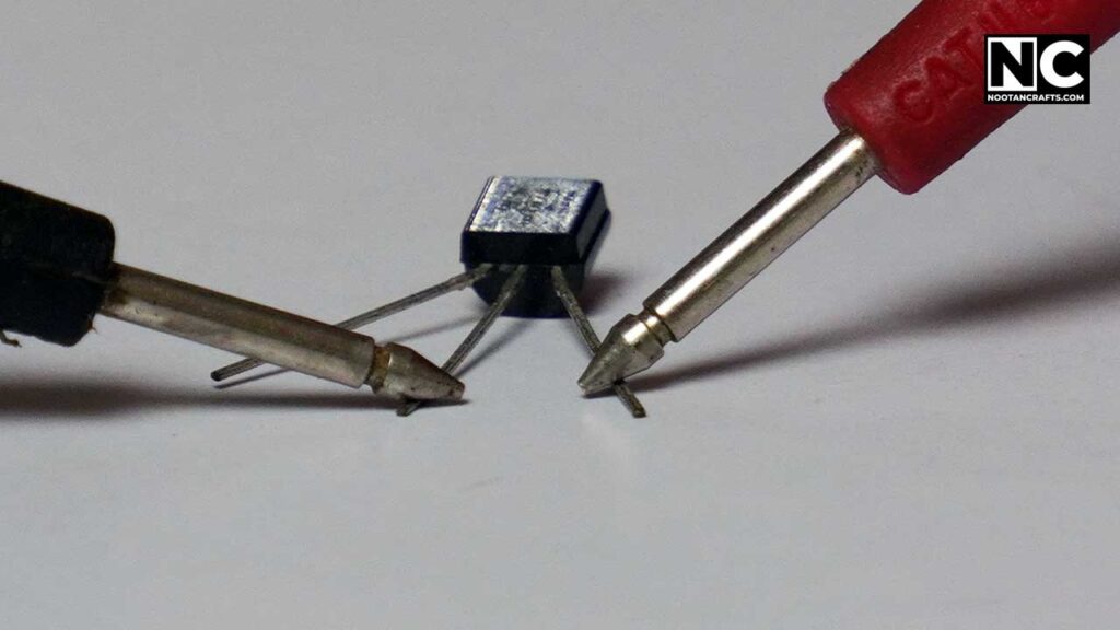
Test the Collector-Emitter Junction:
- Connect the red probe to the collector (C) and the black probe to the emitter (E).
- There should be no reading or high resistance.
- Reverse the probes: connect the black probe to the collector and the red probe to the emitter. There should be no reading or high resistance.
NPN Transistor Testing Chart
| Test Condition | Red Probe Position | Black Probe Position | Expected Result | Interpretation |
| Base-Collector (Forward Bias) | Base | Collector | Voltage drop (0.6V – 0.7V) | Junction is functional |
| Base-Collector (Reverse Bias) | Collector | Base | No reading (open circuit) | Junction is functional |
| Base-Emitter (Forward Bias) | Base | Emitter | Voltage drop (0.6V – 0.7V) | Junction is functional |
| Base-Emitter (Reverse Bias) | Emitter | Base | No reading (open circuit) | Junction is functional |
| Collector-Emitter | Collector | Emitter | No reading (open circuit) | Junction is functional |
| Collector-Emitter (Reverse) | Emitter | Collector | No reading (open circuit) | Junction is functional |
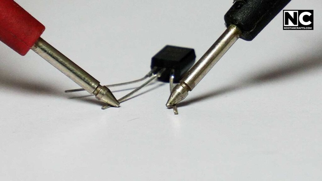
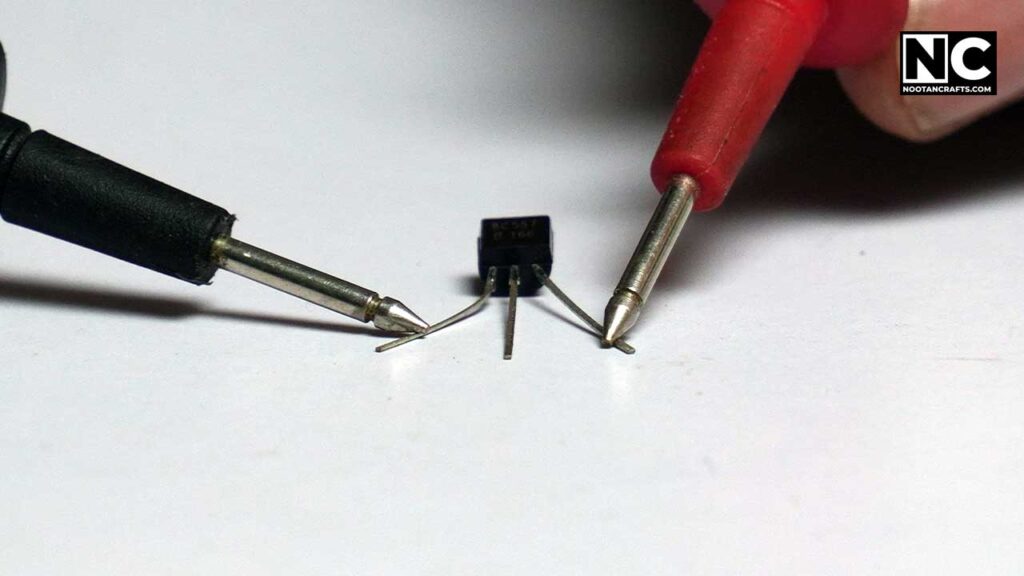
Steps for Testing PNP Transistors
The PNP transistor’s testing is just reverse. When you connect the lead to any junction, there should be a reading in the reverse direction. Here is a step-by-step process.
Keep the multimeter dial in the diode testing mode as above.
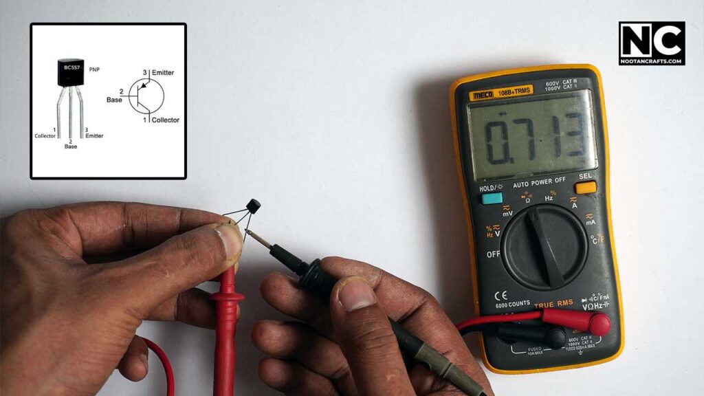
Identify the transistor leads base (B), collector (C), and emitter (E). I am testing a BC557, a PNP transistor with the same pinout as the BC547.
- Pin 1 – collector
- Pin 2 – base
- Pin 3 – emitter
Test the Base-Collector Junction:
- Connect the black (negative) probe to the base (B) and the red (positive) probe to the collector (C).
- An okay PNP transistor will show a voltage drop (around 0.6V to 0.7V).
- Reverse the probes: connect the red probe to the base and the black probe to the collector. There should be no reading or high resistance.
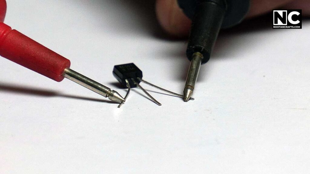
Test the Base-Emitter Junction:
- Connect the black probe to the base (B) and the red probe to the emitter (E).
- A working PNP transistor will show a voltage drop (around 0.6V to 0.7V).
- Reverse the probes: connect the red probe to the base and the black probe to the emitter. There should be no reading or high resistance.
Test the Collector-Emitter Junction:
- Connect the black probe to the collector (C) and the red probe to the emitter (E).
- There should be no reading or high resistance.
- Reverse the probes: connect the red probe to the collector and the black probe to the emitter. There should be no reading or high resistance.
PNP Transistor Testing Chart
| Test Condition | Red Probe Position | Black Probe Position | Expected Result | Interpretation |
| Base-Collector (Forward Bias) | Collector | Base | Voltage drop (0.6V – 0.7V) | Junction is functional |
| Base-Collector (Reverse Bias) | Base | Collector | No reading (open circuit) | Junction is functional |
| Base-Emitter (Forward Bias) | Emitter | Base | Voltage drop (0.6V – 0.7V) | Junction is functional |
| Base-Emitter (Reverse Bias) | Base | Emitter | No reading (open circuit) | Junction is functional |
| Collector-Emitter | Collector | Emitter | No reading (open circuit) | Junction is functional |
| Collector-Emitter (Reverse) | Emitter | Collector | No reading (open circuit) | Junction is functional |
Special Notes:
- Forward Bias: The red probe is on the positive side (anode/base), and the black probe is on the negative side (cathode/collector/emitter).
- Reverse Bias: The red probe is on the negative side (cathode/collector/emitter) and the black probe is on the positive side (anode/base).
- A functional diode or transistor junction should show a voltage drop in forward bias and no reading in reverse bias.
- For transistors, no reading in the collector-emitter junction in either direction indicates the transistor is not shorted.
Frequently Asked Questions (FAQs)
First, check the battery and test leads. Also, ensure the dial is set correctly for your measurement. If the problem persists, the multimeter may need calibration or repair.
Yes, but extreme caution is required. Always follow safety guidelines to avoid electric shock. Moreover, ensure the voltage and current must be within the range of a multimeter.
OL stands for “overload” or “open loop.” It indicates that the measured value is outside the range of the multimeter or that there’s no continuity (an open circuit).
Of course! Most digital multimeters support testing both AC and DC currents. Please ensure the correct dial setting before testing.
You can use the continuity mode to identify cables. Connect one probe to one end of the cable and the other probe to the opposite end. If the multimeter beeps, the cable is correctly identified.
Set the multimeter to continuity mode. Place one probe on each wire. If those two wires are connected, the multimeter will beep.
A diode symbol (➤|) or a sound wave symbol typically represents the continuity mode.
You can verify a multimeter’s authenticity by testing it against a known source, such as a battery. If the reading matches the expected value, your multimeter is working properly.
Set the multimeter to AC voltage mode (V~). Insert the probes into the power outlet. If the outlet is functioning correctly, the reading should be around 220V.
Set the multimeter to DC voltage mode (V-), more than 12 volts. Connect the red probe to the positive terminal and the black probe to the negative terminal of the 12V source.
At least once a year or according to the manufacturer’s recommendations.
How Do You Use a 7-Function Digital Multimeter? – Conclusion
Using a 7-function multimeter might seem daunting at first, but it’s not. You just need to identify what you’re measuring/testing and set the meter accordingly, for example, voltage, current, resistance, continuity, or diode. Always set the multimeter at a higher range than the voltage and current you’ll measure.
Another important thing is to make sure the multimeter’s probes are connected to the right ports. Usually, you don’t need to change the probes unless you’re testing current. The black probe is always connected to the COM port, while the red probes need to be interchanged according to the measurement.
That’s it. Hopefully, this article has provided you with some value. Please comment below if you have any questions about using a 7-function digital multimeter. Thanks for reading. Until next time, keep crafting!


I already knew how to use a damn multimeter, I don’t need a damn guide.
You can write better, but I liked it. follow me on instagram. Thanks
Which multimeter have you used in this tutorial? Is it available in England?