
A multimeter measures voltage, current, and resistance, and each one is measured in a completely different way. Voltage you measure across a running circuit. Current you measure through it, which means breaking the circuit and putting the meter in the gap. Resistance you measure on a circuit with the power off — always. Get those three straight and everything else on the dial is a variation.
Get them confused, and you can destroy the meter or hurt yourself, and there is one specific mistake that does it. That one comes first, before any how-to.
The tool for this job
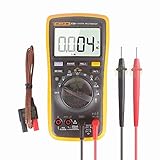
Last update on 2026-09-14 / Affiliate links / Images from Amazon Product Advertising API
What’s Inside!
Read This Before You Touch a Live Circuit

Test leads left in the amps jack, then touched to a live voltage
The current input is designed to have almost no resistance, because an ammeter has to let current pass through it without affecting the circuit. Touch those same leads across a live voltage and you have connected a piece of wire straight across the supply. The meter becomes a short circuit — an industry safety guide puts it plainly: with the probes in the amps jack, “the multimeter effectively becomes a phase-to-phase short,” and it “can cause an arc flash” (EC&M).
This is not a rare accident. It is the normal outcome of measuring current, forgetting to move the red lead back, and then measuring a voltage — which is exactly the order most troubleshooting happens in.
- Make moving the lead back part of the measurement. Finish a current reading, move the red lead to the VΩ jack immediately. Not later.
- Check the jack before every probe touch on a live circuit. Look at where the leads are plugged in, then look at the dial, then probe.
- Check the CAT rating on your meter before it goes near wall power. CAT II covers outlets and plug-in appliances; CAT III covers fixed wiring, feeders and distribution panels; CAT IV covers the service entrance and outdoor lines. Choose a meter rated for the highest category you might use it in (Fluke).
- Many cheap “7-function” meters carry no CAT rating at all. That is a statement about what happens during a fault, not about accuracy. An unrated meter is fine on batteries, components and low-voltage DC. It does not belong across a wall outlet.
- Never measure resistance, continuity or diodes on a live circuit. Those modes work by sending the meter’s own small test current out through the probes. External voltage arriving back gives nonsense readings at best and damages the meter at worst. Power off, and on anything with capacitors, wait.
- Buy from a brand that publishes its specifications, and inspect the leads before use. Cracked insulation near the probe tip is the most common fault, and it is where your fingers are.
- One hand where possible on live work, and safety glasses. Current across the chest is what kills; an arc flash is what burns.
The Three Jacks, Which Are the Whole Problem
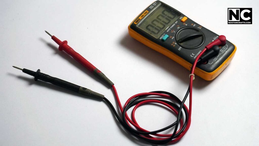
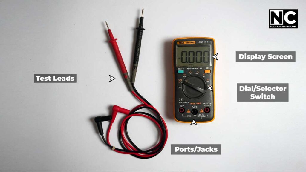
- COMBlack lead. Always. It never moves
- VΩRed lead for voltage, resistance, continuity, diode
- mA / 10ARed lead for current ONLY – move it back afterward
- DialSelects the function and, on a manual meter, the range
One correction to something written everywhere, including the older version of this page: the leads are not “positive and negative.” Black is COM — the reference point — and red is the measuring probe. On DC, that distinction looks academic, because a reversed pair just shows a minus sign. On AC, there is no polarity to get wrong at all. Thinking of black as the reference rather than as negative is what makes the current measurement below make sense.

Measuring Voltage
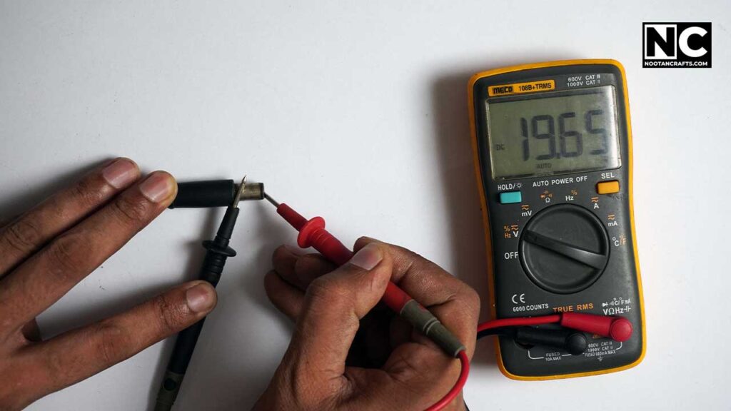
- Black in COM, red in VΩConfirm it with your eyes, not your memory.
- Dial to V~ for AC or V― for DCWall outlets and household wiring are AC. Batteries, USB supplies and car electrics are DC.
- On a manual-range meter, pick a range above what you expectTesting a 9 V battery, use the 20 V range. Testing a wall outlet, use the range above your local supply – 200 V for a 120 V country, 750 V for a 230 V one. Too low a range shows an overload; guessing too low on line voltage is how meters die.
- Probe across the two pointsVoltage is always a difference between two places, so both probes must touch something. A single probe reads nothing meaningful.
An autoranging meter removes step 3 entirely, and for a beginner that is worth more than any other feature on the box — it is one fewer thing to get wrong while your hands are near live wiring.
Measuring Current
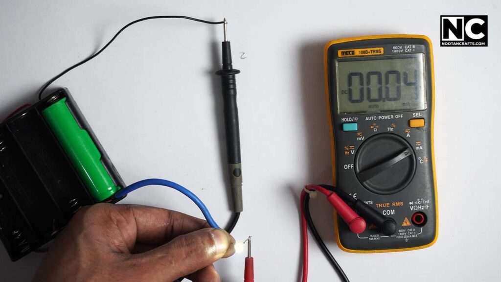
This is the awkward one, and it’s physical rather than procedural: current has to flow through the meter. You cannot measure it by touching two points. You have to open the circuit and place the meter in the gap, so it becomes part of the circuit.
- Power off firstYou are about to disconnect something.
- Red lead into mA or 10AUse 10A if you have no idea what to expect. The mA jack is usually the one with the small fuse behind it.
- Dial to A~ or A―Match AC or DC to the circuit.
- Break the circuit and bridge the gap with the probesThe meter now carries the whole current the load draws.
- Power on, read, power offTake the reading and get out. A meter left in a high-current circuit heats its shunt.
- Move the red lead back to VΩ before anything elseDo this now, while you are still thinking about it. This is the step that hurts people.
Continuity and Resistance
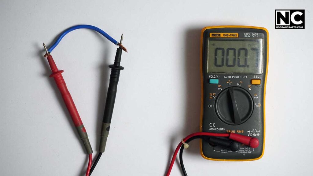
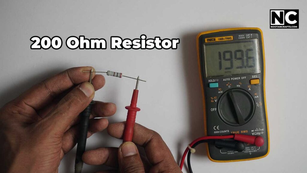
These are the same measurement, just reported differently. Continuity beeps below some threshold, usually around 30 ohms; resistance gives you the number. Both work by pushing a small test current out of the probes and measuring what comes back, which is why the circuit must be dead—anything else feeding voltage in corrupts the reading.
- Black in COM, red in VΩ, dial to the beep symbol or to Ω.
- Touch the probes together first. It should beep and read near zero. That checks the leads and gives you the lead resistance, which matters when measuring anything under a few ohms.
- Continuity is for fuses, switches, and suspect wires. Beep means intact; silence means broken.
- Take components out of circuit to measure them. A resistor soldered into a board reads whatever the rest of the board reads in parallel, not its own value.
Don’t chase perfect resistance numbers. Components have tolerances — a 100 Ω resistor showing 95 or 105 is behaving exactly as specified, and a 5% part is allowed anywhere between 95 and 105 by definition.
Testing a Battery Properly
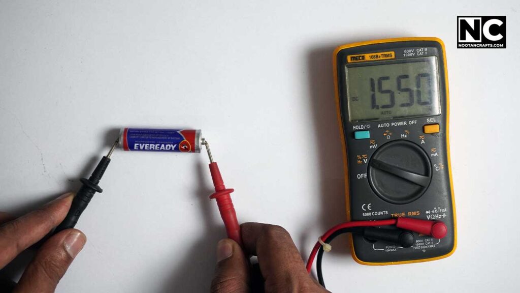
DC volts, range above the battery’s rating, red on positive and black on negative. A fresh AA reads about 1.5 V; a 9 V block reads about 9.5 V when new.
A dead battery can read perfectly on an open circuit. This is the single most misleading measurement a beginner takes. Voltage measured with nothing connected says almost nothing about whether the cell can deliver current — an exhausted AA will happily show 1.4 V and then collapse the instant a load draws from it. A meter’s dedicated battery-test range exists precisely because it applies a small load while reading. If your meter has one, use it. If it does not, measure the battery while it is in the device and switched on.
Testing a Diode
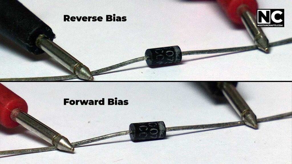
A diode passes current one way and blocks it the other, so the test is simply to try both directions. Diode mode puts a small voltage across the part and displays the drop.
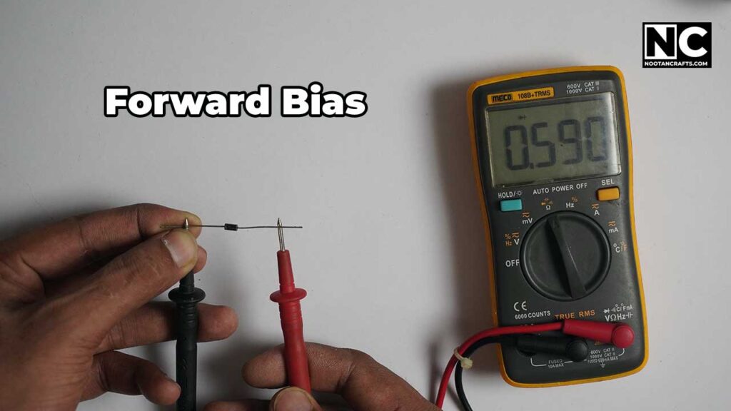
Forward bias
Red probe on the anode, black on the cathode. A healthy silicon diode shows 0.6 to 0.7 V; germanium, 0.2 to 0.3 V; and an LED, 1.8 V and up.
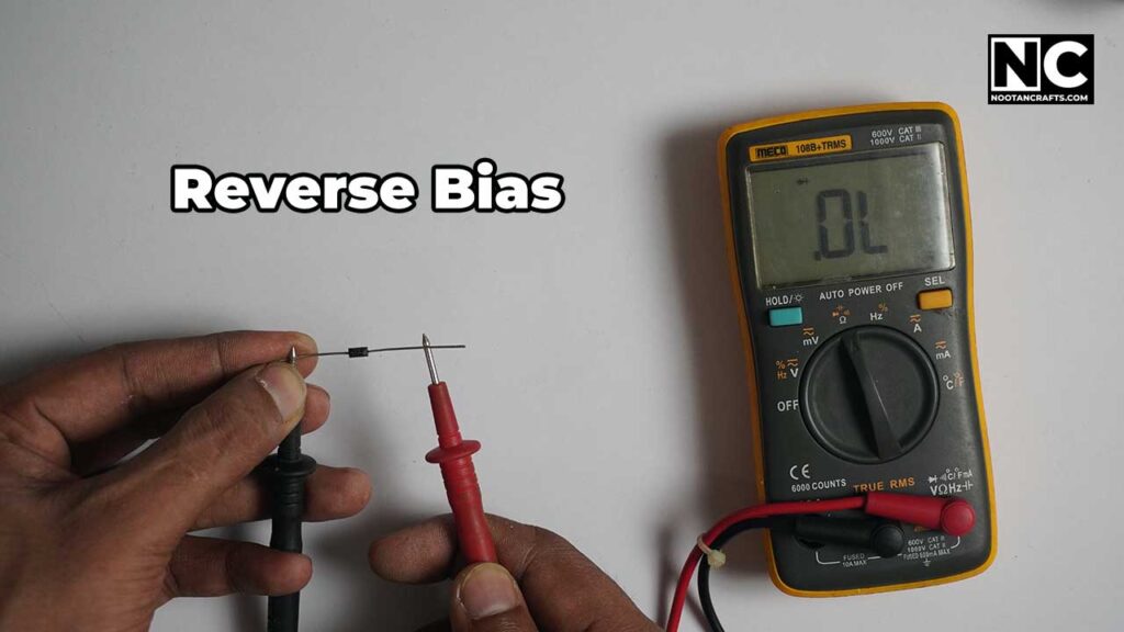
Reverse bias
Swap the probes. A healthy diode shows OL or a blank display – no conduction at all. Conduction in both directions means it is shorted; conduction in neither means it is open. Either way, replace it.
| Direction | Red probe | Black probe | A good diode shows |
|---|---|---|---|
| Forward | Anode | Cathode | 0.6 – 0.7 V silicon, 0.2 – 0.3 V germanium, 1.8 V+ on an LED |
| Reverse | Cathode | Anode | OL, or a blank display |
Testing a Transistor
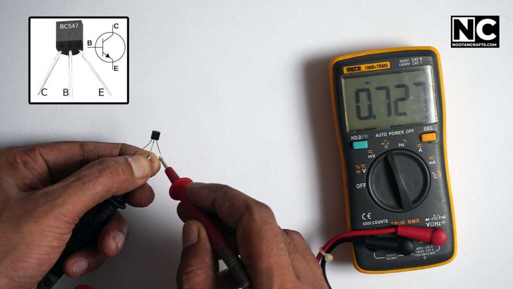
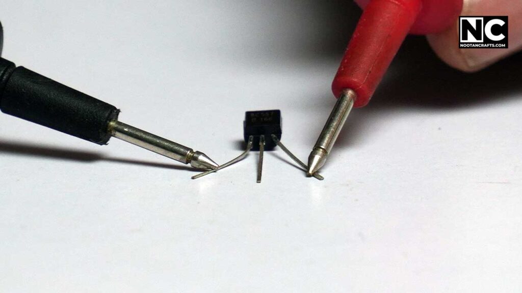
A bipolar transistor is two diode junctions sharing a base, which is why the same mode tests it. On an NPN – a BC547, say – the black probe stays on the base for reverse checks, and the red probe goes on the base for forward checks. Each junction is tested both ways.
Base to collector
Red on the base, black on the collector: a normal forward drop of roughly 0.6 to 0.7 V.
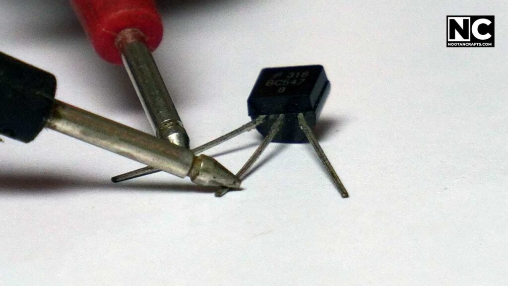
Reverse the probes, and it should read OL.
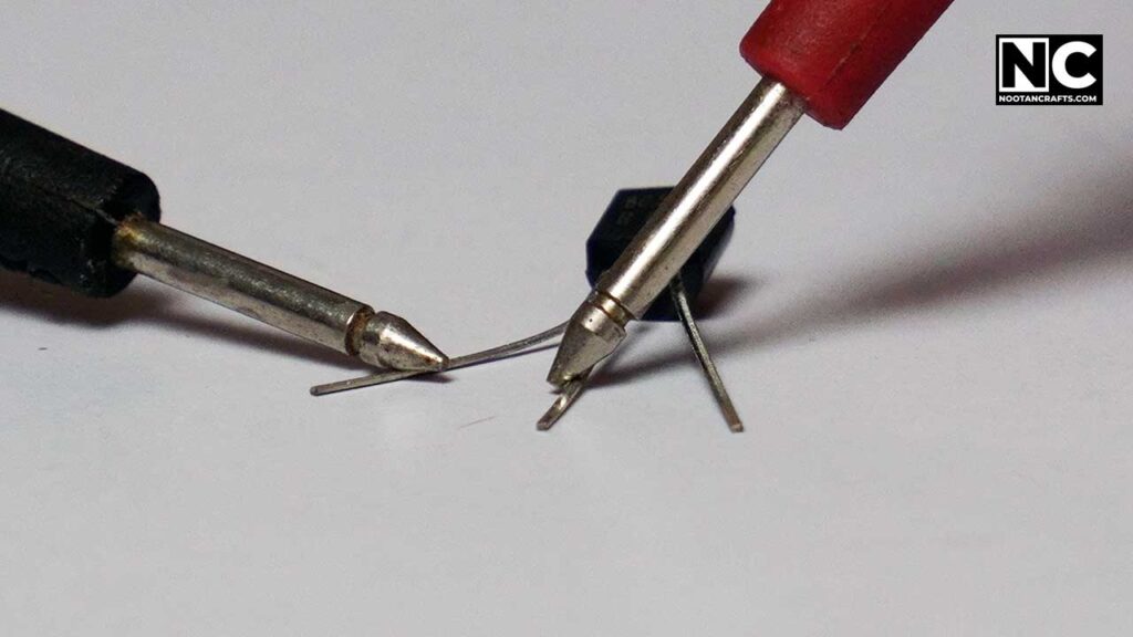
Base to emitter
The same pattern. Red on the base, black on the emitter gives the forward drop.
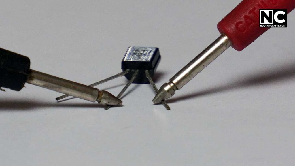
Reversed, it should read OL.
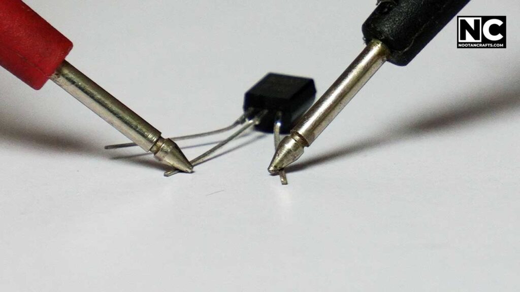
Collector to emitter
This one should read OL in both directions. Anything else means the transistor is shorted.
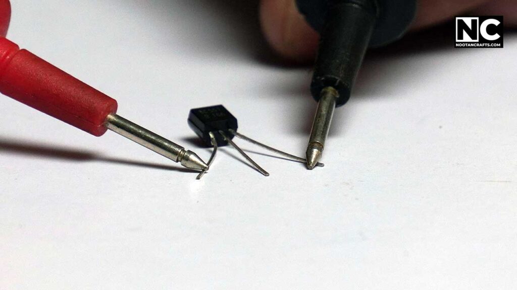
PNP transistors
On a PNP such as a BC557, the whole pattern inverts: black probe on the base for the forward checks, red on collector and emitter. Same pinout, same expected readings, opposite polarity.
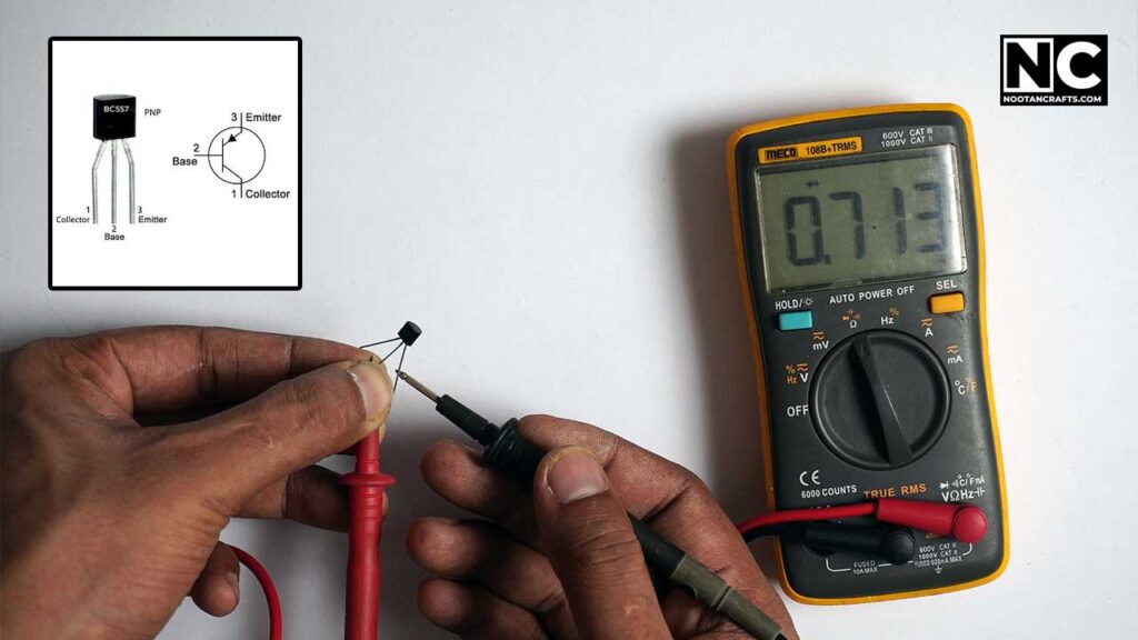
The whole test in one line: any junction that conducts in both directions is shorted, and any that conducts in neither is open. That catches the great majority of failed transistors.
Common Questions
Why did my multimeter blow its fuse?
Almost certainly the leads were in the amps jack when a voltage was measured. The current input is nearly a dead short by design, so putting it across a supply draws whatever the supply can deliver until the fuse opens. The fuse doing its job is the good outcome; on a meter with an unfused input, or on a supply that can deliver serious fault current, the outcome is an arc.
What does OL or 1 on the display mean?
Overload – the value is above what the selected range can show. On a manual meter, go up a range. In resistance or diode mode it usually means the opposite of a fault in the meter: an open circuit, infinite resistance, nothing connecting the two probes.
Can I test a wall outlet with a cheap multimeter?
Only if it carries a CAT rating suitable for the job – CAT II at minimum for outlets and plug-in appliances, CAT III for anything in fixed wiring or a distribution panel. Many inexpensive 7-function meters carry no CAT rating at all. That rating describes what the meter does during a fault, not how accurate it is, and it is the one specification worth paying for.
Why does my battery read fine but the device is dead?
Because voltage with nothing connected does not test whether the cell can supply current. A worn AA can read 1.4 V open and collapse under any real load. Use the meter’s battery-test range, which applies a load while reading, or measure it in the device with the device switched on.
AC or DC – how do I know which to use?
Anything from a wall outlet or household wiring is AC. Anything from a battery, a USB supply, a solar panel or a vehicle is DC. Measuring AC on the DC setting typically shows near zero, which reads exactly like a dead circuit – and mistaking a live circuit for a dead one is the dangerous half of that error.
Do I need to take a component out of the circuit to test it?
For resistance, usually yes – other paths on the board sit in parallel and drag the reading down. For continuity on wires, fuses and switches, no. For diodes in circuit, the reading is often usable but not trustworthy; lift one leg if the result looks odd.
If a reading is not making sense, the fault is nearly always the jack, the dial or the range — in that order. Check all three before you conclude anything about the circuit. For dimensional measuring rather than electrical, the companion tool is the vernier caliper – and the brands worth trusting.



I already knew how to use a damn multimeter, I don’t need a damn guide.
You can write better, but I liked it. follow me on instagram. Thanks
Which multimeter have you used in this tutorial? Is it available in England?